
<img height="1" width="1" src="https://www.facebook.com/tr?id=3900557156680409&amp;ev=PageView &amp;noscript=1">
Skip to content
HoG_Additive_Manufacturing_RGB_box-1

CNC milling or 3D printing?

Which process is right for your part?

CNC milling is precise and often cost-effective for larger production runs. 3D printing excels with complex geometries, small production runs, and short lead times. Often, a combination of both is the most cost-effective solution.
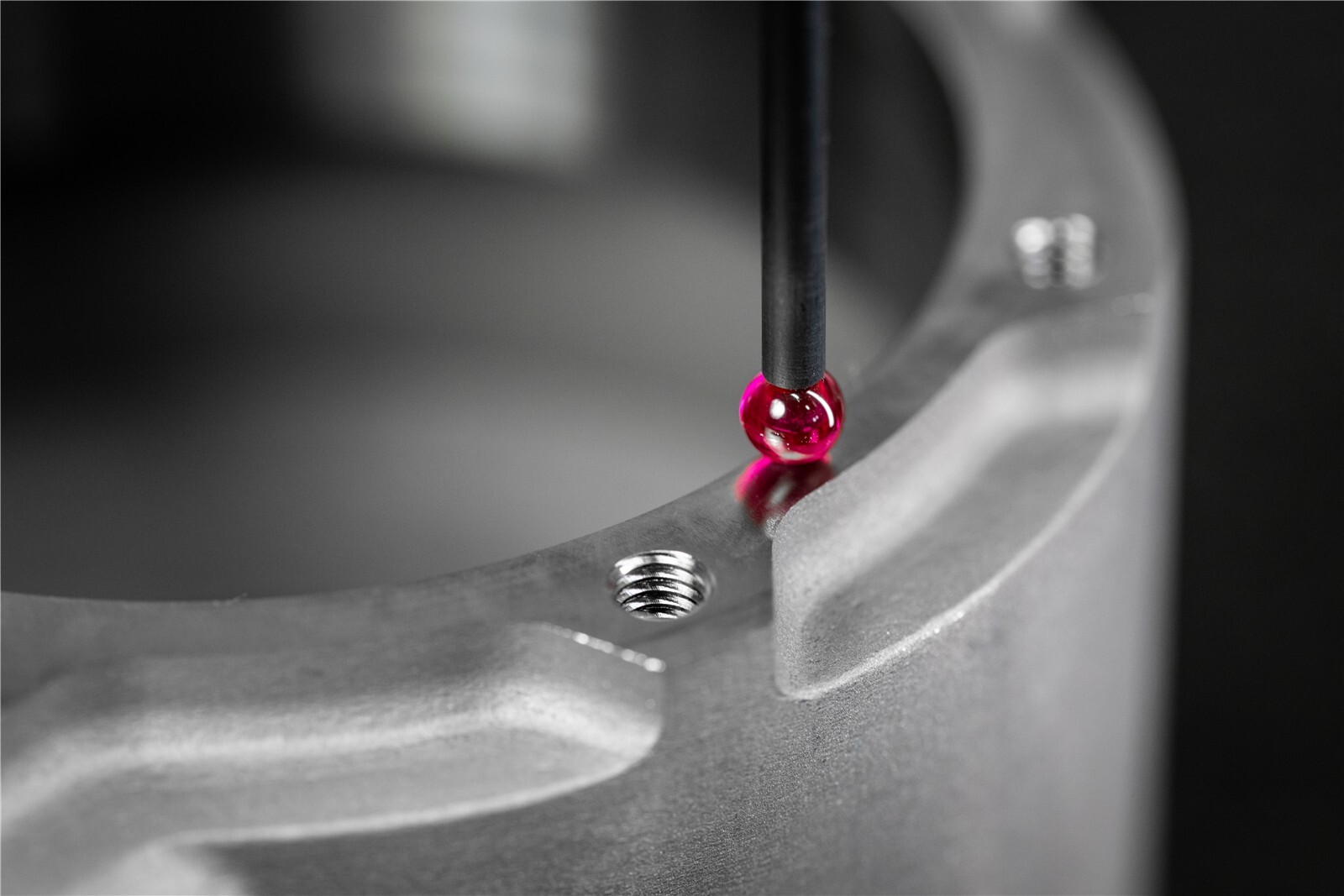
A probe inspects a CNC-machined functional surface on a 3D-printed metal component

The Processes at a Glance

  • CNC milling removes material from a blank. It achieves tight tolerances and good surface finishes, but requires clamping devices, tool access, and—depending on the part—multiple setups.
  • 3D printing builds the part layer by layer directly from the CAD data. Internal channels, undercuts, and lightweight structures incur no additional tooling costs.
  • Hybrid manufacturing prints the complex geometry and then machines only the functional surfaces on the CNC machine.

When 3D Printing Is the Better Choice

Complex Geometries

Internal channels, lightweight structures, and integrated features can be printed, but are difficult or nearly impossible to mill without significant effort.
Short delivery time

A valve housing that would typically have taken 1.5 months to manufacture was completed in just one week using 3D printing.

Less material used

Only the material contained within the part is printed. When milling from solid stock, a large portion of the blank is turned into chips.

When CNC Milling Is the Better Choice

Tight Tolerances

Fits, bores, and sealing surfaces can be milled or turned with a precision of ±0.01 to 0.05 mm. Printed surfaces are reworked for this purpose.

Simple Parts in Mass Production

If the geometry is simple and the production volume is high, machining is usually more cost-effective per part.

Material and Surface

If a material cannot be 3D-printed or if the entire surface must be very smooth without any post-processing, the solution is to use a CNC machine.

A Direct Comparison of CNC Milling and 3D Printing

CriterionCNC Milling3D Printing
Tools and FixturesMilling tools and clamping devices; special fixtures depending on the partNone
Design changesNew CAM program; new fixture may be requiredAdapt the CAD file and reprint
GeometryLimited by tool access; internal channels are rarely possibleHigh design freedom, including internal channels and lightweight structures
Tolerances±0.01 to 0.05 mm on functional surfacesDepends on the process; tight fits require post-processing
Material usageMaterial removal from the blank, extensive machiningMaterial is present only where the component requires it
Lead timeDepends on clamping setups and manufacturing stepsProduction starts immediately based on the CAD data
QuantityCost-effective even for larger production runsIdeal for prototypes, small production runs, and replacement parts

Rule of thumb: The more complex the part and the smaller the production run, the more 3D printing makes sense. The simpler the geometry and the more surfaces that require tight tolerances, the more a CNC machine is the better choice.

How We Combine 3D Printing and CNC Machining

Through our Printfactory, we coordinate printing, post-processing, and measurement in a single process chain. You receive a ready-to-install component from a single source.

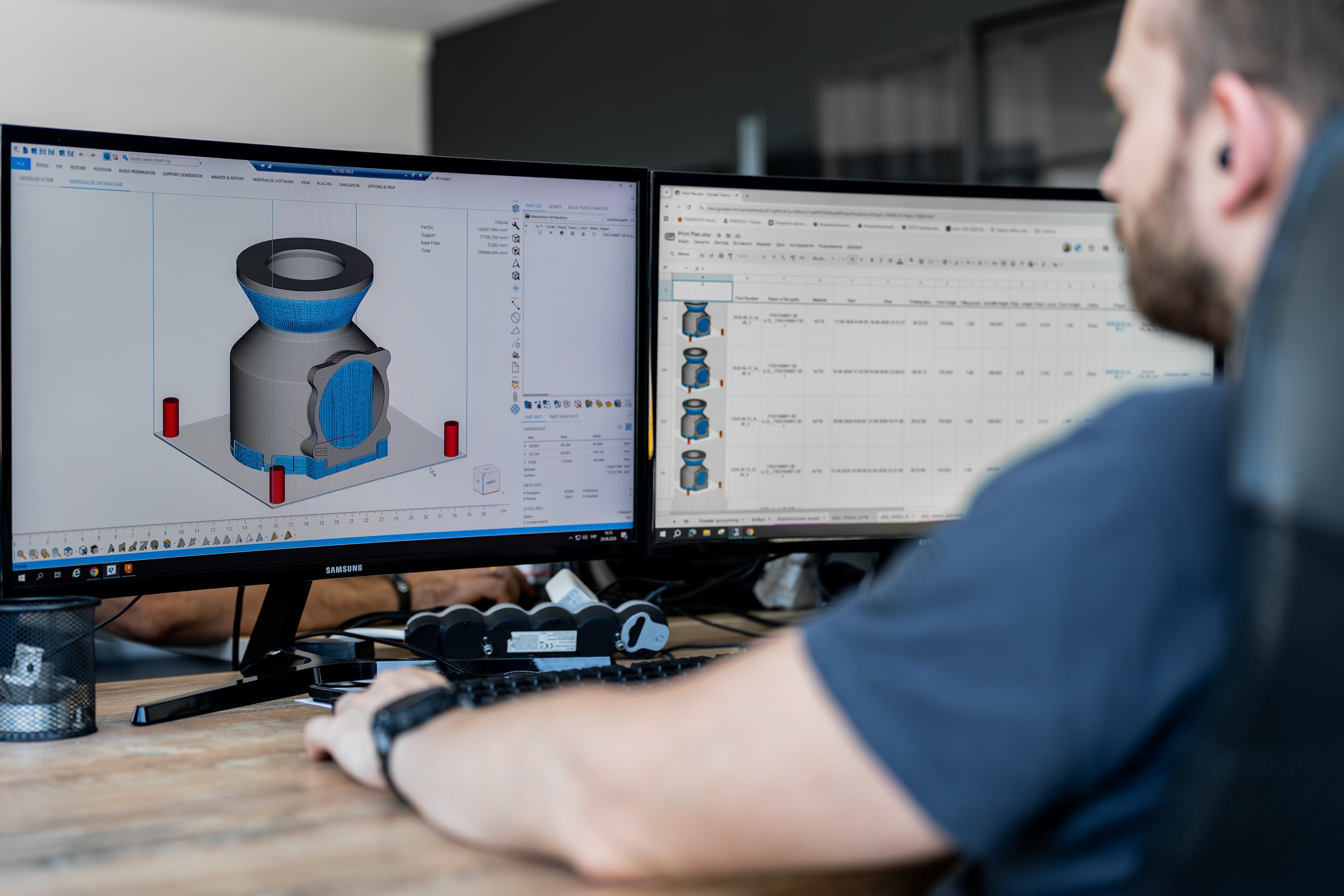
An engineer prepares a component on the screen for 3D printing

1. Check the data

We review your CAD data, determine the orientation and support structures, and plan which surfaces will be machined later.
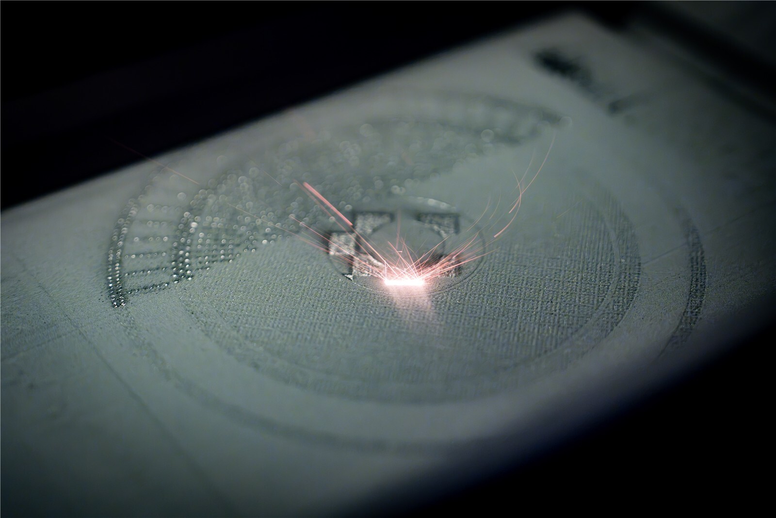
A laser melts metal powder in a powder bed, layer by layer

2. Print

The laser fuses the metal powder layer by layer. Internal channels and complex shapes are created without the use of tools.

An employee wearing protective gear removes residual powder from the metal 3D printer

3. Dust Removal

Any remaining powder is removed, after which the component is stress-relief annealed and blasted.
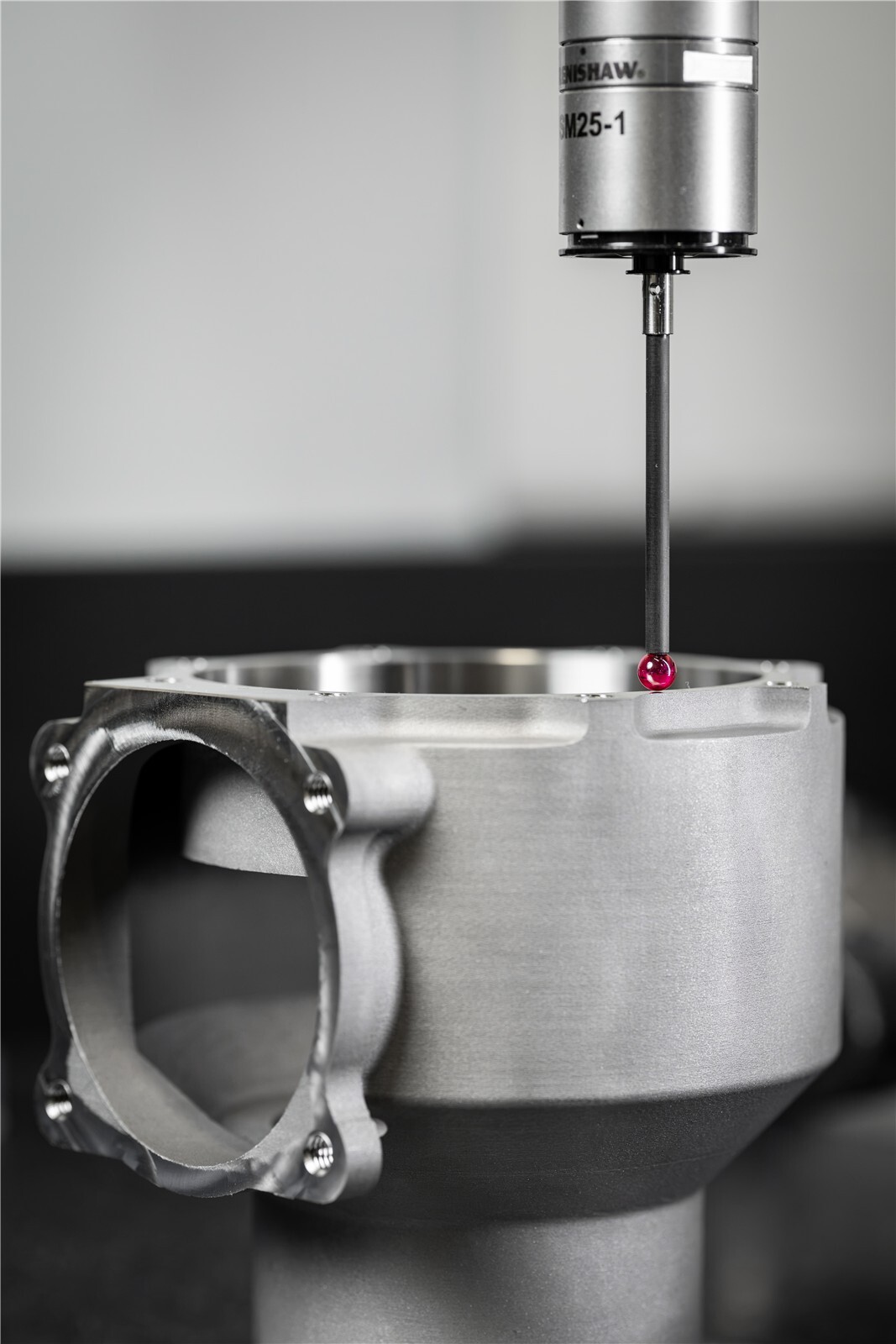
Quality inspection of a 3D-printed metal part on the measuring machine

4. CNC and Measurement

Fits, holes, and sealing surfaces are finished on the CNC machine and then measured.
Use Cases: Which Process Is Right for Which Component?

Three components from our projects, three different answers. Do you recognize your component?

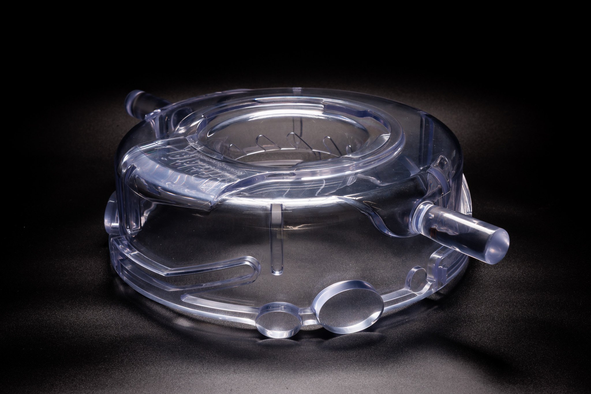
Transparent precision component produced using 3D printing, vacuum casting, and CNC machining

3D Printing, Vacuum Casting, and CNC

A transparent functional component for a machining system. Printed master model, vacuum casting in Hei-Cast, and CNC machining only on fits and holes: ±0.01 to 0.05 mm, where it counts.

Fan housing made of AlSi10Mg, 3D-printed and CNC-machined at the mounting surfaces

3D-printed, CNC-machined

A lightweight housing made of AlSi10Mg for an aircraft engine. Printed, stress-relieved, and sandblasted. Only the mating surfaces are CNC-turned and milled.
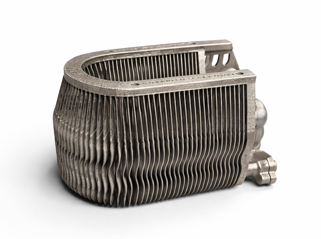
Multichannel satellite radiator made of Ti-6Al-4V titanium with fine fins

Slats that a router can't reach

A titanium radiator with thin-walled channels and fine fins, which would be hardly economical to manufacture using traditional machining methods. Printed with a layer thickness of 40 µm in 14 hours.

Can your components also be manufactured more cost-effectively?

Upload your part and get an instant estimate of the price and delivery time.

1️⃣ Online Calculator

Get prices and delivery times for prototypes, replacement parts, and small production runs in just a few seconds.

2️⃣ Custom Inquiry

For complex components, series production projects, or special requirements, our experts will advise you personally.

Onur Yildirim, Head of Sales for Additive Manufacturing at Hoffmann AM
Not sure which method is right for you? Talk to us.

Onur Yildirim

Head of Sales, Additive Manufacturing

 +49 89 83 919 898 

  3d@hoffmann-am.com 

 Fislisbach, Switzerland